Why analogue sounds wider, and how much of it is components being slightly wrong
Every hardware versus plugin comparison ends the same way. The analogue one sounds wider and more alive, nobody can say why, and the conclusion is that something about circuits resists being written down.
Most of it can be written down. One mechanism in particular is measurable, rarely mentioned, and easy to demonstrate: the two channels of a piece of hardware are not the same as each other.
Two channels are never identical
Components are sold with tolerances, and the tolerance is the whole specification. A resistor marked 1% is guaranteed only to be within 1%. Film capacitors are commonly 5 or 10%, electrolytics far worse, inductors worse again.
A filter’s corner frequency depends on those values, so it inherits their error. For a simple RC the corner is one over 2πRC, and the errors stack:
metal film 1% + film cap 5%      corner spans -5.7% to +6.3%   = 2.08 semitones
carbon comp 5% + film cap 10%    corner spans -13.4% to +17.0% = 5.21 semitones
inductor 10% + cap 5%            corner spans -7.0% to +8.1%   = 2.60 semitones
Those are worst cases and real units cluster nearer the middle, but the scale is the point. Two channels of the same equalizer, built to the same schematic on the same day, can have their bands sitting a semitone or more apart. On a Pultec-style inductor design the tolerance on the inductor makes it worse than on an RC one.
Nothing is faulty here. Both channels are inside specification. They are just not the same.
What a small mismatch actually does
Take a realistic case rather than a worst case. Two channels, the same nominal 1 kHz bell at +6 dB, and one channel’s parts sitting 3 percent off, which is comfortably inside a film capacitor’s tolerance.
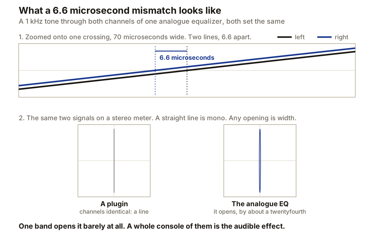
Send a 1 kHz tone through both and the two outputs are 6.6 microseconds apart. Draw them on top of each other and you see one line, because 6.6 microseconds is a hundred and fiftieth of a cycle.
Subtract one channel from the other and something is left over. It is small: the difference is about a twenty-fourth of either channel, which is -27.6 dB. Measured the other common way, as side against mid, the same thing is -33.6 dB, because side is half the difference. Both numbers appear below and they describe one phenomenon.
Do the same subtraction on a plugin and you get the bottom panel: a flat line. Not a small residue, not a quiet one. Nothing, because the same arithmetic ran twice on the same input and produced the same answer twice.
That leftover is the mechanism. It is not yet the effect.
Run the numbers on what one band actually buys and the honesty is uncomfortable: a difference that small leaves the two channels correlated at 0.99913, which is mono for any practical purpose. One EQ band, three percent out, does not make a record sound wide.
What makes it audible is that hardware never does this once. Every stage has tolerances, every channel has several stages, and a console has dozens of channels, each varying independently. Decorrelation from independent stages accumulates:
1 stage      side -33.6 dB     correlation 0.9991
4 stages     side -27.6 dB     correlation 0.9965
24 stages    side -19.8 dB     correlation 0.9793
That is the version worth arguing about, and it is precisely why the one company that models this varies every channel of a console rather than one band of one equalizer.
And it only happens where you equalised
One tone shows that a difference exists. Looking across the whole frequency range shows where it lives, which turns out to be the more useful fact.
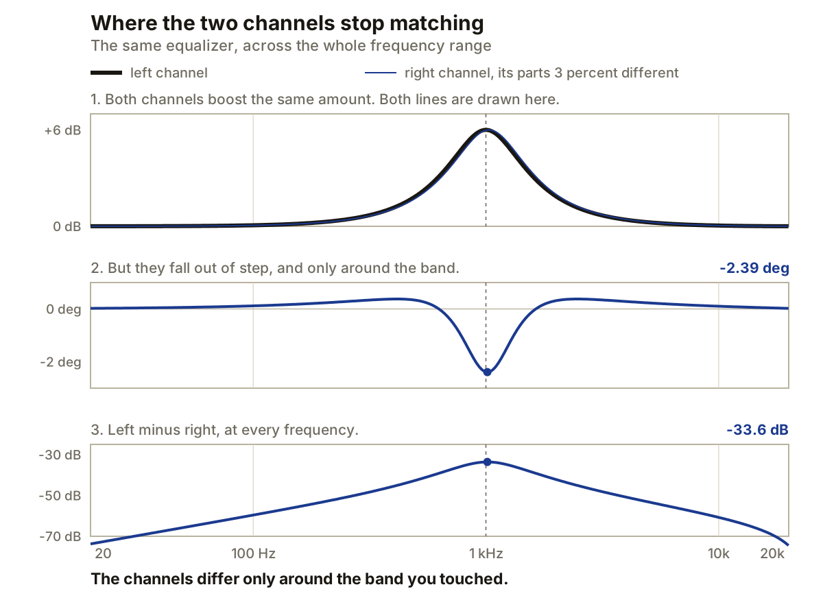
On a magnitude plot the two curves are still indistinguishable. The largest level difference anywhere is 0.24 dB, which is nothing.
The phase is where it happens. The largest phase difference is 2.39 degrees, and it lands at the band centre, because that is where a filter’s phase moves fastest. Subtract one channel from the other and what remains peaks at 33.6 dB below the centre signal, at 1014 Hz, falling away to below -60 dB outside the band.
That is the finding worth keeping. The decorrelation is not spread across the spectrum. It appears exactly where you equalised and nowhere else, which is why boosting with an analogue EQ seems to open the image up while the same boost in software does not. The plugin runs identical arithmetic on both channels, so its difference signal is not small, it is zero.
Phase does more of the work than level
Both kinds of mismatch decorrelate, but not equally.
gain difference          side energy       phase difference    side energy
0.25 dB                    -36.8 dB         1 degree             -41.2 dB
0.50 dB                    -30.8 dB         2 degrees            -35.2 dB
1.00 dB                    -24.8 dB         5 degrees            -27.2 dB
2.00 dB                    -18.8 dB        10 degrees            -21.2 dB
Five degrees of phase difference decorrelates about as much as a full decibel of level difference, and five degrees is easy to get from ordinary component spread. This is also why the effect concentrates around filter corners: level differences between channels stay small everywhere, but phase differences spike wherever the response is bending.
Why 34 dB down is not small
A residual at -34 dB looks negligible written down. It is around the level that null-test discussions commonly wave through as inconsequential, though that convention is a rule of thumb from practice rather than anything established.
It matters more than the number suggests, though not without limit. A -34 dB artefact added to both channels equally is a quiet distortion product. The same energy appearing as a difference between the channels is the raw material of stereo localisation instead, which is a thing hearing is specialised for. How much is needed before it is reliably audible is not something this piece can settle, and the correlation figures above suggest one band is well under it.
That is the trap in the usual measurement. Measure the change to one channel and the number looks dismissible. The number that matters is the change between the channels, and nobody measures that.
What this does not explain
Channel decorrelation is the biggest piece. It is not the only one, and it would be just as lazy to claim it is.
Non-linearity needs only one channel. Transformer hysteresis, tube and transistor transfer curves, and core saturation at low frequencies all add harmonic content that no linear filter produces, and which harmonics appear is most of what people mean by the character of a saturator. The digital version has a failure mode of its own, aliasing, which is the usual reason a distortion plugin sounds cheap. This is precisely what Volterra-kernel and neural modelling exist to chase, and it is a genuinely separate mechanism.
Level dependence is the other. A real inductor’s behaviour changes as you drive it, so an analogue EQ’s curve at -20 dBFS is not quite its curve at -3. A naive digital filter is identical at every level by construction.
Anyone claiming the whole difference is channel mismatch is overselling it, the same way the magic camp oversells the other direction.
The industry already conceded this
The strongest support for the tolerance argument comes from a company with every commercial reason to argue the opposite.
Brainworx built Tolerance Modeling Technology by cataloguing component tolerances in a Neve VXS 72 console, reported elsewhere as more than 150 of them, measuring one channel as a reference, then generating variation consistent with what would leave a factory. Their own explanation of why it works cites small phase differences, unbalanced centre frequencies and centre offsets, and says the effect is most obvious on stereo material, where running different channel variants left and right is audible in both tone and width.
A plugin developer could have said the magic was unreproducible. Instead they identified the mechanism, modelled it, and sold it.
The part nobody enjoys
None of the above is the largest variable in most comparisons you will watch online.
The largest variable is that the two files are not at the same level, and the listener knows which is which. Half a decibel reliably reads as better, which is why matching levels before you judge changes what people buy. Once levels are matched and labels hidden, the reported differences shrink hard, which is exactly why arguments about this run for hundreds of forum posts without resolving: both sides are describing real listening sessions, and only one side controlled for the thing that dominates.
So the honest summary has three parts. Channel decorrelation is real, measurable and the main reason hardware sounds wider. Non-linearity and level dependence are real and separate. And most of what a casual comparison demonstrates is neither of those, it is methodology.
Producer’s note
You can hear the mechanism in about five minutes with any EQ plugin that lets you unlink the channels.
Put a mono source in, split to two channels, and boost the same band on both by the same amount. Nothing happens to the image, because the two sides remain identical. Now move one channel’s frequency by three percent, which on a 1 kHz band is 30 Hz, and leave everything else alone. The tone barely changes and the image opens.
Then check what you actually built: flip one channel’s polarity and sum to mono. What you hear is the difference signal, and it will be a narrow band sitting where you equalised, at roughly the level the diagram above predicts. That residue is the whole trick, and it is the thing a perfectly matched pair of digital filters can never produce.